From Richard Dawson to Steve Harvey, Family Feud is a game show that many people enjoy watching. Without a doubt, many families have fantasized about how they would perform if given the chance. Now, thanks to the Internet, you can easily access thousands of questions to test your skills. But, answering the questions is only half the fun of Family Feud. The remaining half comes from the interaction with the game itself. In order to provide a more gratifying and entertaining experience, in this project we will attempt to automate the game of Family Feud so you can get a chance to put your family to the test.
Required Materials:
- A computer (Windows 10 was used in this project)
- 1x ESP32 development board
- 2x Buttons
- 2x LEDs
- 1x 4×4 Keypad
- 1x I2C LCD
- Several feet of wire
Project Overview
In this article, we will develop and assemble the hardware that will be used to implement this project. We will first outline the requirements of the hardware, so we are able to decide what and how we will meet those requirements. For the hardware it must be able to:
- read two buttons and determine who pressed their button first.
- notify the players and host who pressed their button first.
- take host input to control the flow of the game.
- output information to the host.
- output the game screen so players may follow along the game.
In order to output the game screen, a simple web server will be used. This will be covered in more detail in the software portion of this project. Therefore, we will only be addressing the first 4 requirements.
Game Control
Since we want to use a webserver, we should pick out a microcontroller that already has all the functions we require. The one I used is the ESP32, linked here. The ESP32 has WiFi capability built in, and can be programmed similarly to the Arduino. In addition, it has enough GPIO pins to accomplish the task at hand, as well as internal storage which will be beneficial to us later.
Faceoff Buttons
During the Family Feud Faceoff, two players are asked a question and must buzz in to answer the question. Whoever presses their button first is given the opportunity to answer first. To accomplish this, two buttons will be required. In addition, we need a method of notifying the players who answered first in case they are both pressed at around the same time. Two LED’s will be used, and the button that is pressed first will flash, while the other will be locked out.
Instead of using a discrete button and LED, I used a button with an integrated LED. Specifically, I used 60mm arcade buttons. If you opt to use a discrete LED, remember to use a current limiting resistor!
Host Control
In order for the host to control the game, they must have an array of buttons available to them. They must be able to show/hide up to 8 answers, increment/decrement the number of strikes, give points to teams, and play/stop the theme music. In order to accomplish this with fewer pins, a 4×4 keypad is used. This keypad only uses 8 pins, and allows 16 buttons to be indexed.
I used these keypads. There are several different varieties, but these were simple (and cheap) enough for me.
Lastly, in order to output information to the host, a 16×2 LCD is used. While we could theoretically use a normal LCD, this would come with a high pin cost. We have already dedicated 12 pins to other IO’s, so we should try to minimize the required pins if possible. To do this, an I2C LCD is used. The LCD uses another chip to convert an I2C signal into an LCD signal, and allows us to reduce the number of pins required. The specific LCD used is linked here.
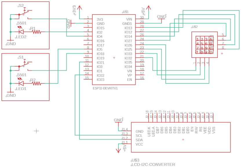
Hardware Schematic
The full schematic is shown below. Notice that three wires are required for each faceoff button. This is because both the button and LED have one terminal wired to ground, while the other terminal is connected to the microcontroller. An internal pullup resistor is used to bias the button input, so that when the button is pressed, the input signal goes LOW.
Only the I2C to LCD converter is shown, as all wiring from the converter to LCD is internal, and there is nothing for us to do there.

Remember how I said you needed several feet of wire? This is because you want some flexibility with the buttons. What happens if the two players are sitting across the table from each other? Instead of having them move, you can simply move the button toward them.
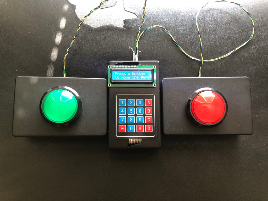
Results
Instead of just leaving everything barebones or on a breadboard, I got some enclosures that could be used to put the buttons and internals inside. This made the project look considerably better, and also made it more permanent and less likely to fail. I, however, do not recommend placing the ESP32 into the enclosure until the project is completely finished, as you must press the BOOT button during programming. This is much more difficult when the ESP32 is inside an enclosure, so this should be left until the end.
Simple test code was written to test out each function of the hardware. The code checks all inputs, and either blinks the correct button LED, or displays which button was pressed to the user through the LCD.
/* Family Feud ESP32 Hardware Test Code
 *
 * This code simply tests the hardware to make
 * sure everything is connected correctly.
 *
 * Keypad and LCD libraries are utilized, and should
 * be downloaded before attempting to use this code.
 */


// Include your libs.
#include "Keypad.h"
#include "LiquidCrystal_I2C.h"

#define buttonPinA 18     // yellow wire
#define LEDPinA 5         // green wire
#define buttonPinB 4      // yellow wire
#define LEDPinB 2         // green wire
#define LCDAddress  0x27  // I2C address for LCD

const byte ROWS = 4; //four rows
const byte COLS = 4; //three columns
char keys[ROWS][COLS] = {
  {'1','2','3', 'A'},
  {'4','5','6', 'B'},
  {'7','8','9', 'C'},
  {'*','0','#', 'D'}
};

byte rowPins[ROWS] = {32, 33, 25, 26}; //connect to the row pinouts of the keypad
byte colPins[COLS] = {27, 14, 12, 13}; //connect to the column pinouts of the keypad

Keypad keypad = Keypad( makeKeymap(keys), rowPins, colPins, ROWS, COLS );

LiquidCrystal_I2C lcd(LCDAddress, 16, 2);

void setup() {

  lcd.init();
  lcd.backlight();

  pinMode(buttonPinA, INPUT_PULLUP);
  pinMode(buttonPinB, INPUT_PULLUP);
  pinMode(LEDPinA, OUTPUT);
  pinMode(LEDPinB, OUTPUT);

  newMess=true;

}

void loop() {

  if(newMess) {
    newMess=false;
    lcd.clear();
    lcd.setCursor(0, 0);
    lcd.print("Press a button");
    lcd.setCursor(0, 1);
    lcd.print("to move the game");
  }

  if(!digitalRead(buttonPinA)) {
    blinkButton(LEDPinA);
  }
  else if(!digitalRead(buttonPinB)) {
    blinkButton(LEDPinB);
  }

  char key = keypad.getKey();

  if (key != NO_KEY){
    switch (key) {
      case '1':
        youPressed(key);
        break;
      case '2':
        youPressed(key);
        break;
      case '3':
        youPressed(key);
        break;
      case '4':
        youPressed(key);
        break;
      case '5':
        youPressed(key);
        break;
      case '6':
        youPressed(key);
        break;
      case '7':
        youPressed(key);
        break;
      case '8':
        youPressed(key);
        break;
      case '#':
        youPressed(key);
        break;
      case '*':
        youPressed(key);
        break;
      case 'A':
        youPressed(key);
        break;
      case 'B':
        youPressed(key);
        break;
      case 'D':
        youPressed(key);
        break;
    }
  }
}

void blinkButton(int pin) {
  playRing = true;
  for(int i = 0; i < 4; i++) {
    digitalWrite(pin, HIGH);
    delay(250);
    digitalWrite(pin, LOW);
    delay(250);
  }
  return;
}

void youPressed(char press) {
  lcd.clear();
  lcd.setCursor(0,0);
  lcd.print("You pressed ");
  lcd.print(press);
  newMess = true;
  delay(1000);
}
In the next article, we will develop the code which will be responsible for the flow of the game, as well as the code which generates and updates the game server.
